
Well, it’s been a while. Between finishing out my EE degree, moving my life three states away, and setting up at a new job, I’ve barely had time to do anything ham related, let alone some DIY designs. Now that it’s been a few months, I’ve settled in and started busting out the Kicad skills and lab tools to get the wheels turning on a new and exciting long-term project here in the shack.
After weeks of tinkering, tuning, and troubleshooting, I’m proud to reveal the pre-alpha version of what I’ve been toiling away at during my absence from the internet: an open-source, full-duplex 15W FM satellite rig that you can build at home using nothing more than a soldering iron and a multimeter!
This post will be a very high-level overview of my current plan for the rig – how it will all work and what’s going on inside. Later posts will go into way more detail on the various systems and how they all mesh together, but I’m at a point now where I’m confident that this won’t be another one of those projects that never sees the light of day.
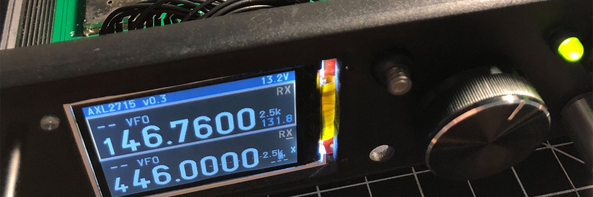
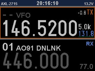
I give you – the AXL-2715 (2m 70cm 15-watt transceiver):
For the Birds
During my last year at Purdue, I helped set up an absolutely bangin’ satellite ground station for 2m/70cm. After logging nearly 100 contacts on almost every transponder satellite that passes over the Midwest, I realized I was hooked on LEO communications. The downside? If you want to upgrade from your run-of-the-mill dual band, half-duplex HT for talking to the FM birds, you’re going to end up paying a pretty penny. Looking at what’s on the market today: the gold-standard full duplex HT would be the ubiquitous TH-D72A from Kenwood. At around $380, it’s definitely not a budget-friendly radio for someone fresh out of college – and that’s just for 5W of power. If you want to move up to the big boys – for example the all-mode TS-790A (the rig we run at Purdue) – you’re looking at something upwards of $700 if you’re lucky on the used market. I wanted something a bit more reasonable, and a bit more…satisfying…to set up. Of course, I probably chose the most difficult route possible to get on the air with amsat, but there’s something rewarding about making your first QSO with a radio you built yourself.
Simple at Heart
When I first started the planning for this rig, I had to decide right away how deep I wanted to go down the hole of RF design. Some people would start from scratch, building an entire FM frontend from scratch – modulators and mixers galore. Truth be told, if I was going for a full-featured and multi-mode radio with the best performance possible I probably would’ve gone that route. However, I wanted a radio that I could use within a few days of getting the PCBs and not something that would require tinkering for months with the particulars of every RF block element until I got it working. The KISS approach is always a solid choice in situations like this.
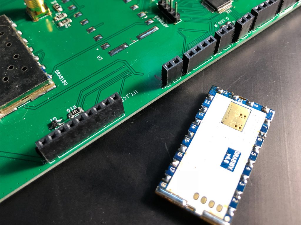
There’s an interesting module series that made some initial waves a few years ago when it was first released – the DRA818 series of FM transceiver chips from Dorji, a chinese manufacturer of RF modules and radios. This module is advertised as a low-cost, all in one solution for building an FM radio with minimal external parts. They come in both VHF (136-174 MHz) and UHF (400-470 MHz) flavors, put out 1W*, and are only $12.28 in quantity 1 from Dorji. So for $24 you’ve got the entire RF chain of a dual-band satellite rig covered. I bought a couple of each and so far they’ve been performing admirably with only a few quirks that I’ll go over in later posts.
Two Boards for Double the Fun
Of course, a measly 1W of power isn’t going to get you very far with satellites. There’s a second half to the RF journey for this rig – one that involves some actual RF engineering skills. Mating to each of these transceiver modules will be a 15W LDMOS power amplifier to give your signals a little extra kick on that long journey to low-earth orbit. And, to help out in the other direction, some low gain (~20dB or so) LNAs will be stuck on the RX path to give these budget modules a fighting chance at decent sensitivity.
This has so far been the most difficult part of the design process – the RF board. I’ve been through five revisions of it since June and it’s still not in a state where I’m ready to send it to a fab. Every time I think I’ve got a solid design, I realize I could be doing something a different and simpler way. Cost optimization while still maintaining an easy-to-build design has definitely shown me why some people get their doctorate in amplifier design.

Oh-So-Fancy Full Color
After I had decided on the RF side of things, the wannabe graphic designer in me started going to work on concepts for a basic UI using a 320×240 TFT LCD. I knew I wanted to make the radio as simple to operate as possible, while still maintaining all the features you’d need to work satellites as well as terrestrial repeaters. One thing was set in stone from day 1 – no menus! I can’t stand navigating through folders and sections trying to find the settings I need. On top of that, menus are annyoing to code in c++, especially when you’ve only got a limited amount of buttons to work with.
Knobs and Buttons and Switches, oh yeah!
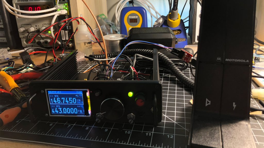
The actual physical controls of the radio were another thing I wanted to keep simple – and this was a decision made out of necessity. The processor chosen to run everything, the STM32F103C, has a limited number of IO pins and I had to balance them among everything on the radio – serial communication between the DRA modules, hardware lines for PTT and T/R relays, the SPI bus for the TFT – these all take up a good majority of the usable IO on the chip. I was left with just enough pin space for two rotary encoders with switches, two buttons, and a bi-color LED. Not exactly the front-panel overload of some rigs but it should (hopefully) be more than enough for all the features packed into this radio. Plus, I like to think that a minimal front panel makes the radio look nice and clean. That’s the idea anyway, once I get something a little bit more professional than holes dremeled out of a piece of plastic (that 3D printer can’t get here soon enough).
Getting a little bit specific
To wrap things up, I’m going to quickly present the current goals for this radio project and what the thing is going to be able to do when all is said and done.
- 15W full-duplex operation on 2m and 70cm, FM only with CTCSS/DCSS
- 12V operating voltage with a max current draw of around 5A
- 2.5KHz VFO steps (limited by the DRA modules, for FM this should be perfectly fine)
- Basic memory system and CAT controllable via USB for satellite tracking programs
- Hand-solderable dual-layer PCBs able to be made in any fab house
- Easy-to-obtain parts from any major vendor
- Total cost of all parts & boards under $150 – this is in quantities of 1
- Completely open source – all schematics, board files, and code published for anyone to tinker with
There’s still a huge amount of design work, troubleshooting, and protoyping to be done before this gets anywhere near a usable, finished product. Hopefully I’ve done a decent job explaining my ideas and ambitions, and I’d love to hear your thoughts, suggestions, and snarky comments on how you’d do things differently.
Where I’m At Today
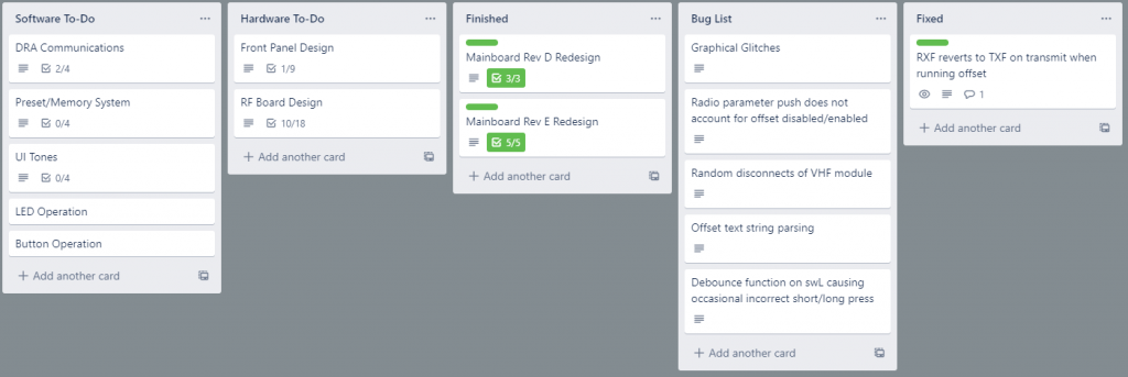
As I wrap up, you might be asking yourself “well how much of this thing is actually built?” Well, so far the first revision of the mainboard has been built and seems to be working fine. Other than a few changes to the power supply and some connectors it’s likely in a close-to-final state. I’ve got most of the UI and backend code built up as well – you can pretty much use the radio as a real radio right now. RF wise, I’ve got no filtering or amplification on the DRA modules and they’re just putting out the 300mW I’ve got them limited to at the moment. Great for local simplex and repeater contacts but nearly worthless for LEO stuff. Still, I’m sure some of you reading this understand the joy that comes with hitting that power switch and having everything finally work as you intended.
Bonus Content – Operational Video
Until next time, catch you on the air and go play some radio. 73!
Sounds fascinating. I look forward to further updates..
In my testing, the DRA modules will actually runs much more fine than 2.5kHz steps. I think you can do as arbitrarily fine as the serial protocol allows. And you can constantly update on Rx, good for tracking Doppler. It will NOT update while transmitting, unfortunately.
I built a PoC of this for Maker Faire a number of years ago (no amps though!), but never went anywhere with it. I love that you’re making this happen!
Other thoughts I had for mine: If you’ve got an available serial port, add a GPS, and the ability to enter orbital parameters so the radio can automatically compensate for doppler, and display on the screen az-el angles to help the user point their antenna. The F103 hopefully has enough math to do a bit of trig. 🙂
the problem I’ve been running into is that the DRA modules seem to self-limit to about 1 frequency update every second or two. Not a very fast refresh time at all. I haven’t tried sending smaller tuning steps to the modules, might have to give that a go and see what happens…
In regards to GPS, serial, etc, the F103 could probably do it but I’m out of IO as it stands right now. I’ve got enough for a USB port which I fully plan to support some rudimentary form of CAT control and that’s about it. I’m trying to fight feature creep as much as I can and the limited IO is definitely helping in that regard.
Thanks for the input!
Very cool! Do you have your work-in-progress code and design files up somewhere for pull requests or are you holding off until your first release?
Waiting until the initial release for now. I don’t really want a bunch of armchair developers poking holes in my subpar C code just yet. I’ll wait till they get their hands on the hardware before letting them go fix all my mistakes.
Hi there!
Very nice project! But, can i see sources?
Thank you!
Hi Eugen,
Unfortunately, this project never got off the ground. The DRA modules proved to be too unreliable. I do have long term plans for a satellite rig but for now they’re on hold pending other projects.