
As well as being a ham radio operator, I also am a huge rail buff. As such, I had long wanted to add a railroad radio to my collection. Unfortunately, the only ones to be found for sale were either old radios from the 80’s with limited feature sets, or newer Astro radios from the big M that were way more than I was willing to pay for a radio.
Fortunately I was able to stumble on a for-parts Motorola Spectra on ebay for a very, very decent price with shipping. The radio was advertised as untested, but pulled from a working environment. I jumped on the item and within a week it was at my door.
So began a not-so-fun journey into the mystical ways of railroad-grade equipment and poor documentation.
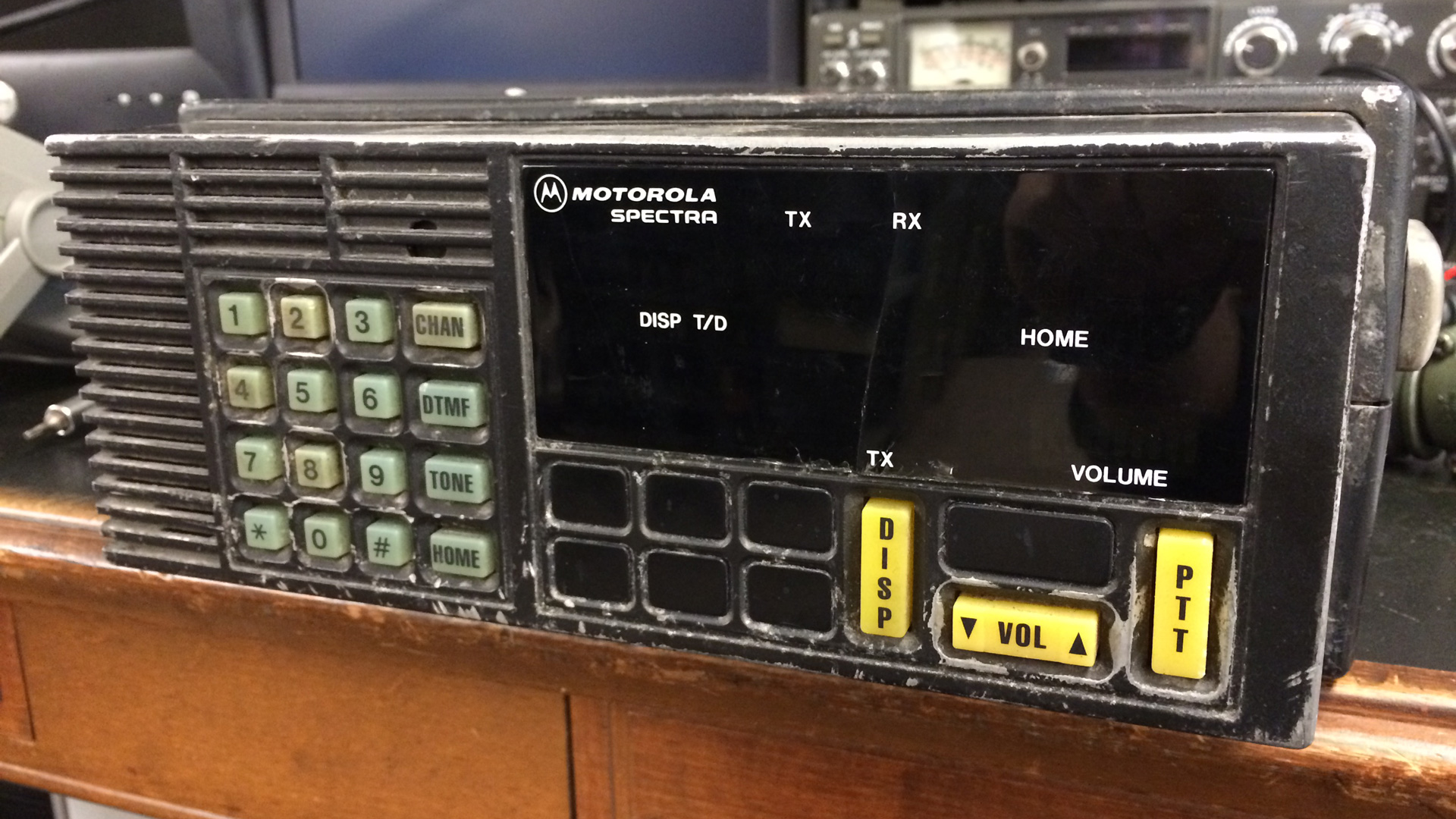
When the unit arrived, it looked a bit worse for wear. The case was scratched and beat up on all sides, which was to be expected of a 15+ year old radio that had seen daily railroad service. Buttons were dirty, the screen was cracked, and it had a generous coating of dust and grime that ended up all over my carpet and desk. Nonetheless, it had the appearance (and weight) of a hearty radio that would serve me well.
There are several specifications set forth by the AAR (Association of American Railroads) that dictate how a railroad radio should function. One such spec is that the connectors across all radios should be standardized. Specifically, they should be standardized to military-spec circular connectors that cost nearly $20 each, used. There was very little in the way of information as to the size and type of connectors the radio uses online, so I went through the liberty of figuring it out myself for anyone else that might be looking for a guide.
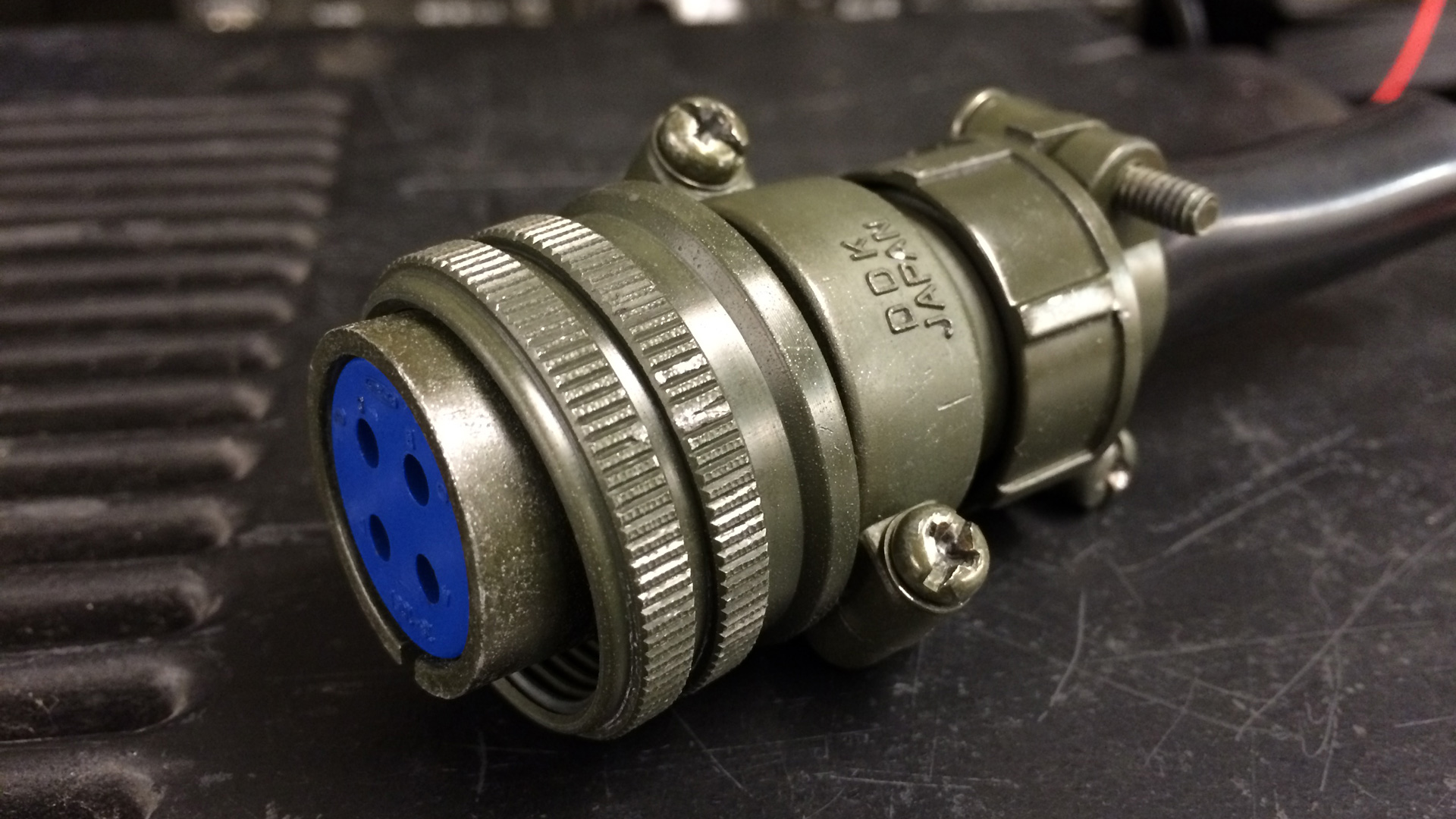
The large power connector is an Amphenol Brand mil-spec connector. It’s in the MS3106 line of connectors; specifically it’s the amphenol MS3106A 18-10S. The first number, 18, specifies the connector size and the second is the specific model of connector. The S signifies that it is a socket, or has female contacts. This is a pretty standard size of connector, and you can sometimes find used versions of this connector on ebay fo relatively cheap. The radio expects either 72V for locomotive operation, or standard 13.8V for vehicle operation. (although I can’t imagine using the radio in any vehicle smaller than a full-sized semi) Pins B & D are used for 12V, with B the ground and D negative.
The other important connector on the radio is the microphone connector, another standard put out by the AAR. The pinout is available on the very useful batlabs page. Once again this is an amphenol job, this time it’s the MS3106 14-6P, and again it can be found for relatively cheap on Mouser or ebay from time to time.
The time came to power up the radio for the first time. When I flipped the switch, the backlights came on and I heard the self-test tone. Unfortunately, shortly afterwards the radio shut itself off. A few seconds later it came back on, this time with FAIL 01/90 splayed across the VFD display. Lovely.
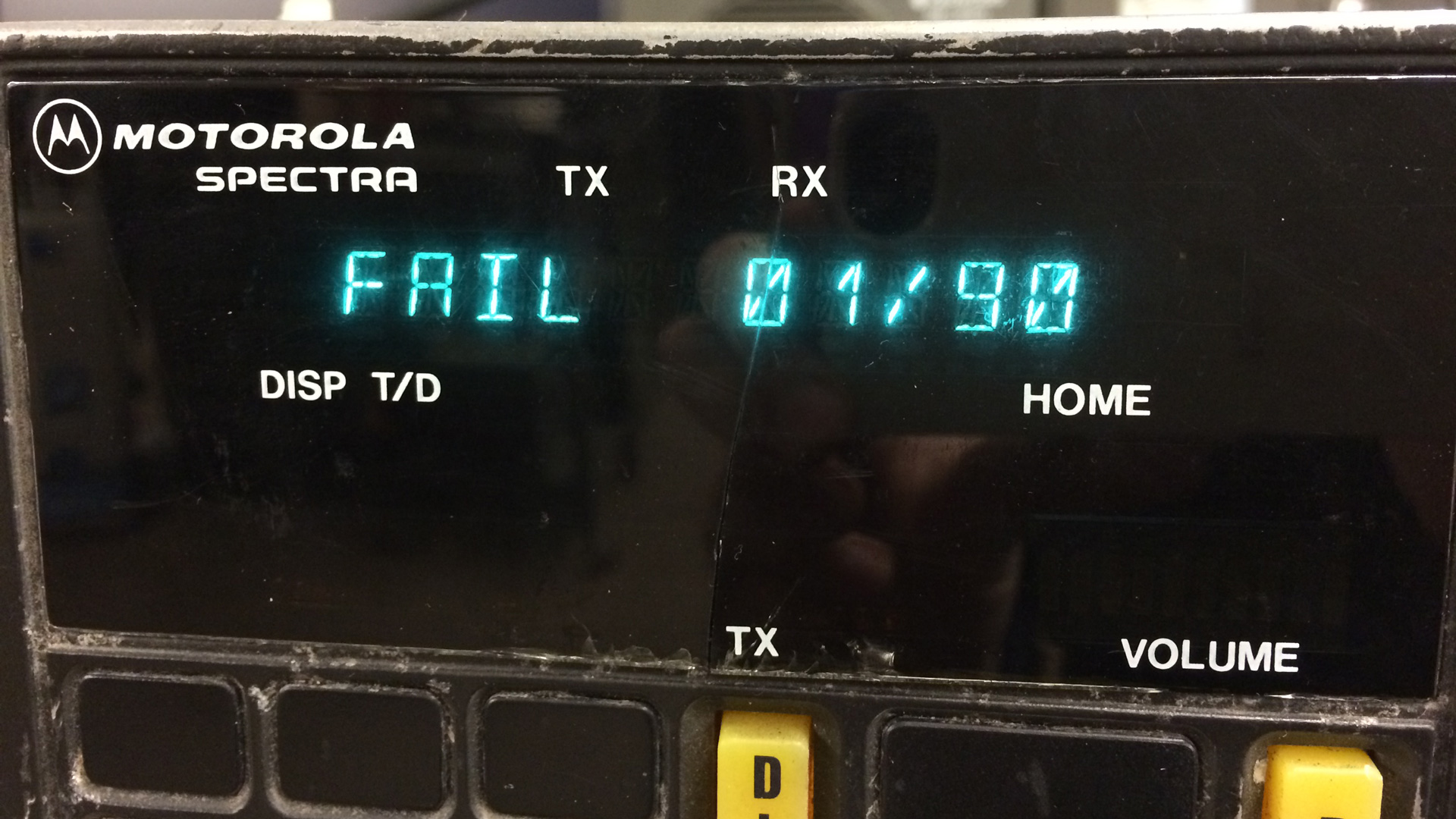
Not the worst thing in the world. We’ve got a functioning display, functioning speaker, and a working power supply. Obviously the radio knows something is wrong, so that’s a plus too. Unfortunately, however, FAIL 01/90 means that we have a general hardware fault, an error almost as helpful as the wonderful error reporting in Windows 10.
In the next part of this article, I’ll be opening up the radio and checking to see just what could be wrong. This could be an easy repair, or a costly mess of a radio that would be better off in the dumpster. Tune in next time for the exciting second part of this disappointing and unengaging saga!
One comment