Hello again everyone! I apologize for the lack of updates. School, as it often does, got in the way once again and I haven’t made real progress on any of my own projects in just under a month now.
Luckily that all changed recently. With nothing better to do on a Saturday night, I set forth a goal of completing the new revision of the redesigned G4HUP panadapter (what I’m now calling the W3AXL Panatap) and getting it installed in my FT-450D. This proved to be both easier and more difficult than I thought. Details inside!
Updates to the Original Post on 12/10/2017
I should’ve made it more clear in my posts, but the component values for the filter section of the panatap board are simply the raw output values from the filter calculator. You will NOT be able to find these values easily, if at all. The filter will work just fine using rounded component values to the nearest widely-available part. Tolerances for low-Q filters like the one on the board are not very strict and the filter will do its job just fine with whatever parts you can get ahold of that are “close enough.”
First things first, the new panadapter board needed to be assembled. Luckily since I’ve built about six of these things I’ve gotten pretty good at not making a mess of the SMD components. Really, 1206 packages aren’t difficult to hand solder if you’ve got fine gauge solder and a somewhat-steady hand. With the new board built, it was time to take it up to the shack for testing.
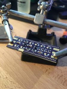
I had a few email requests asking about the physical size of the panadapter compared to the G4HUP board. While I don’t have the original board to compare, I’ve got a standard RTL-SDR stick lying around that serves as a good size comparison. The board is by no means big and should be able to be wedged in to many different radios.

The moment of truth has now arrived. It’s time to take all those subpar simulations, theoretical calculations that I didn’t do, and speculation that everything won’t work and throw them away. It’s time to hook the thing up to a signal and make sure it does what it’s supposed to.
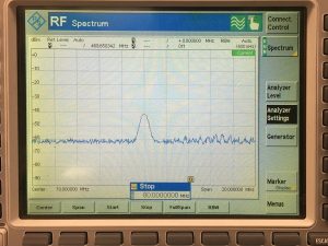
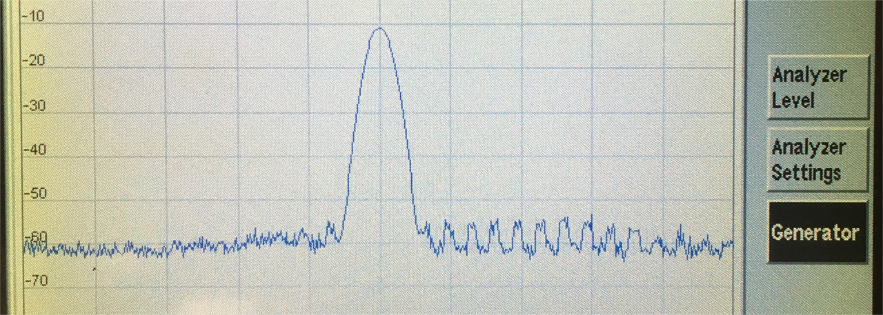
For this very non-scientific test, the adapter was powered with 11 VDC. A -10dBm 70MHz signal was fed into the IF in port, simulating the IF of the FT-450. The output was connected back to the R&S CMU200 and displayed on the SpecAn. I did two tests, one for basic power and one checking the second harmonic as well. In retrospec I probably should’ve checked the third harmonic as well but I have confidence that if one exists, it’s being dealt with by the LPF and won’t be causing any problems.

I was extremely pleased with my test results. Feeding in a -10dBm signal yielded a nearly identical -10dBm output signal! At first I was worried that I had just connected the input straight through to the output, but with power removed the signal drops down to almost -40dBm. The buffer amp was working, and almost perfectly at that! I couldn’t have asked for better results.

With the amplifier built and tested, it was time to jam it in the FT-450 case and see how well it works.
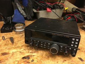
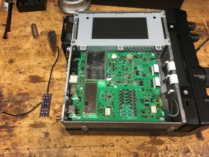
Luckily like the few other Yaesu radio’s I’ve worked on, the FT-450D is extremely easy to work on and has enough room for tinkering with things. Despite it’s small size, there’s just enough room on the underside for securing the adapter board and running the wires to their proper places. Installation procedures were followed pretty much as G4HUP specified originally in his excellent reference page here. This particular board should work for any radio with an IF of around ~70 MHz, and G4HUP has a small list of candidate radios for your experimenting pleasure.
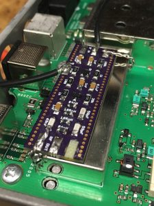
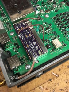
The Panatap by design has nothing on the bottom side but ground vias and pads, meaning that it can rest on top of any solid metal surface on the radio without shorting out. Lacking double sided tape or any sensible mounting material, I opted to go the hard route and use solid wire to solder the board to the shielding can directly. Effectively, I welded the board to the metal can and as a bonus this method doubles as securing the ground for the board. The wires for +RxB and the IF signal were run to their respective locations and the coax for the board output was routed to an SMA jack that I mounted next to the 450’s data port. G4HUP recommends using a ventilation hole for mounting the jack, but this requires tearing down the radio even further and I was short on time. Drilling is always faster and more satisfying anyway.
Below is a video of very shortly after I got the radio put back together. Unfortunately like a bad ham I didn’t log the info of the person in the QSO, nor did I participate in the conversation, but if you’re out there nameless ham: thanks for being a test subject for my project!
Thanks for sticking with me everyone! If you’re interested in building your own Panatap, the Eagle .sch and .brd files have been uploaded to my Github for your downloading pleasure. I’ve debated selling these as kits but I’m against the idea for two reasons:
- The design is 90% G4HUP and I did little to no extra engineering on top of his work other than the filter design and board layout. Any profits belong to his estate alone
- The effort I’d have to expend to assemble and ship kits while also being a full time student would be neigh-impossible
At some point I might consider doing a group run of the boards for discounted pricing but that will only happen if enough interest shows up. Shoot me an email if you think that sounds appealing and if I get enough responses, I’ll make an announcement and get things going.
I hope you enjoyed this project and continue to visit the blog when I post my (very infrequent) updates!
73!

Greetings! Thanks for making this!
I have zero experience creating circuit boards, but I’ve made a few kits in my day. How hard would it be to just send these files someplace and have it built? Or at least the board created?
Using the .brd file included in the github link, you can send it to any PCB fab such as OSHPark and have them create the board for you. You’ll then need to get the components and do the soldering yourself, unfortunately. 1206-sized components aren’t too hard to do by hand though.
I sent you an email but I’ll ask here as well. I’m having a hard time finding L1, L2, L3, and L4. They are 0805 packages vs the 1206 packages for everything else. I’ve checked Mouser and Digikey with no luck. Do you have a good source? Also, what are the tolerances for your capacitors and resistors? I have a lot of surface mount stock but the caps are 10% X7R and the resistors are 5%
Also, the schematic shows C7 as 69F. Did you mean pF or nF. I can’t imagine a 69 farad 1206 part.
Apologies for all of the comments. I’m commenting as I find things out. 59pF and 69pF capacitors are unobtainium. Do you have a source? I’m not sure you meant 69 pF as the schematic shows 69F. I misstated my resistor tolerance above, it’s 1%.
73
NE5U
Mike
Hi Mike! I’ve condensed your comments into a single reply. Apologies for not responding to your email. I saw it come in and forgot to ever send out a response.
I added an update to this post that describes what you and several others have asked about. You can round the component values for the filters up or down to whatever is easiest to obtain. It will make almost no difference to the performance of the filter. I’ll go ahead and update the board and schematic files to the values that I used in my construction of the board. I’ll also include the digikey part numbers I used.
Thanks for the interest. 73!
Very good. I understand about being busy. I basically decided that if I couldn’t get the exact component I would get something close. I have 3 boards made (Osh Park) and assembled I just need to install and test. 73 NE5U Mike PS- thanks for making this available
WOW!! i’m using your schematic to do some versions for IC706MK2G and Yaesu FT817, i’m waiting for the PCB!
Updated digikey BOM for 2018-09-27:
2,399-13192-1-ND
3,399-8131-1-ND
1,311-1160-1-ND
2,399-1203-1-ND
1,541-100KECT-ND
1,311-100NLCT-ND
1,541-39KECT-ND
1,541-220ECT-ND
2,P1.0KECT-ND
1,MMBFJ310CT-ND
1,BFS17WH6327XTSA1CT-ND
2,445-1034-1-ND
2,445-8986-1-ND
Found this project, and it looks great, however, I can’t open the files in EAGLE. Any ideas?
Hi James,
The project may require an older version of EAGLE to properly open. It’s been quite a few years since I originally designed the boards.